PathAway GPS 4
Map Projections Description
Map Projections
Map projections are attempts to portray the surface of the earth or a portion of the earth on a flat surface. Some distortions of conformality, distance, direction, scale, and area always result from this process. Some projections minimize distortions in some of these properties at the expense of maximizing errors in others. Some projection are attempts to only moderately distort all of these properties.
Conformality
When the scale of a map at any point on the map is the same in any direction, the projection is conformal. Meridians (lines of longitude) and parallels (lines of latitude) intersect at right angles. Shape is preserved locally on conformal maps.
Distance
A map is equidistant when it portrays distances from the center of the projection to any other place on the map.
Direction
A map preserves direction when azimuths (angles from a point on a line to another point) are portrayed correctly in all directions.
Scale
Scale is the relationship between a distance portrayed on a map and the same distance on the Earth. In PathAway, Scale is determined by the point calibration settings for the map.
Area
When a map portrays areas over the entire map so that all mapped areas have the same proportional relationship to the areas on the Earth that they represent, the map is an equal-area map.
Different map projections result in different spatial relationships between regions.
Map projections fall into the following general classes.
1. Cylindrical projections result from projecting a spherical surface onto a cylinder.
· When the cylinder is tangent to the sphere contact is along a great circle (the circle formed on the surface of the Earth by a plane passing through the center of the Earth)
· In the secant case, the cylinder touches the sphere along two lines, both small circles (a circle formed on the surface of the Earth by a plane not passing through the center of the Earth).
· When the cylinder upon which the sphere is projected is at right angles to the poles, the cylinder and resulting projection are transverse.
· When the cylinder is at some other, non-orthogonal, angle with respect to the poles, the cylinder and resulting projection is oblique.
2. Conic projections result from projecting a spherical surface onto a cone.
· When the cone is tangent to the sphere contact is along a small circle.
· In the secant case, the cone touches the sphere along two lines, one a great circle, the other a small circle.
3. Azimuthal projections result from projecting a spherical surface onto a plane.
· When the plane is tangent to the sphere contact is at a single point on the surface of the Earth.
· In the secant case, the plane touches the sphere along a small circle if the plane does not pass through the center of the earth, when it will touch along a great circle.
4. Miscellaneous projections
- Include unprojected ones such as rectangular latitude and longitude grids and other examples of that do not fall into the cylindrical, conic, or azimuthal categories
The following sections of projections are divided into the categories of cylindrical, pseudocylindrical, conic, azimuthal and miscellaneous. Each projection is described as to its classification and subclassifcation, aliases, available computational forms (i.e. elliptical, spherical, forward and/or inverse) and summary of usage options. Most projections will also have an example plot of the projection with parenthetical entries in the captions specifying options used to generate the graphic.
In some cases the aliases apply to names given special forms of the projection. For example, the Werner projection which is a special case of the Bonne projection is listed as an alias of the Bonne projection. The usage description does not list the options common to all projections such as the Earth's figure parameters and Cartesian offsets.
Projections - General Parameters
This document describes the parameters of projected maps supported in PathAway. This document does not attempt to describe the parameters particular to particular projection types. Some of these can be found in the GeoTIFF Projections Transform List. This documentation is derived from the PROJ project at https://proj.org.
Geographic Coordinates
All geographic coordinates (lon_0, lat_0, lat_1 etc.) are expressed in latitude/longitude decimal degrees. (ie. Latitude N45.6786 Longitude E8.453)
False Easting/Northing
Virtually all coordinate systems allow for the presence of a false easting (x_0) and northing (y_0). These define the cartesian offsets for the respective x and y axes of the map.
These values are always expressed in meters even if the coordinate system is some other units. Some coordinate systems (such as UTM) have implicit false easting and northing values.
Conic Projections
Basic conic projections involve the transformations to a cone either secant or tangent to the Earth’s surface. Specification of the latitudes of secant intersection are made with the lat_1and lat_2 parameters.
Lambert Conic Conformal
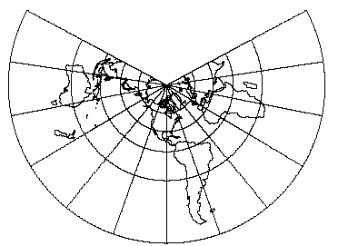
Lambert Conformal Conic projection (2 standard parallels), with shorelines and 30 degree graticule. Central Meridian W90. and standard parallels at N20 and N60 (lon_0=W90 lat_1=N20 lat_2=N60).
LCC with 2 Standard Parallels
|
Name |
Lambert Conic Conformal (2SP) |
|
EPSG Code |
9802 |
|
GeoTIFF Code |
CT_LambertConfConic_2SP (9) |
|
CT_LambertConfConic (9) |
|
|
OGC WKT Name |
Lambert_Conformal_Conic_2SP |
|
Supported By |
EPSG, GeoTIFF, PROJ.4, OGC WKT |
Projection Parameters
|
Param |
Name |
EPSG # |
GeoTIFF ID |
OGC WKT |
Units |
Notes |
|
Lat_0 |
Latitude of false origin |
1 |
FalseOriginLat |
latitude_of_origin |
Angular |
|
|
Lon_0 |
Longitude of false origin |
2 |
FalseOriginLong |
central_meridian |
Angular |
|
|
Lat_1 |
Latitude of first standard parallel |
3 |
StdParallel1 |
standard_parallel_1 |
Angular |
|
|
Lat_2 |
Latitude of second standard parallel |
4 |
StdParallel2 |
standard_parallel_2 |
Angular |
|
|
X_0 |
Easting of false origin |
6 |
FalseOriginEasting |
false_easting |
Linear |
|
|
Y_0 |
Northing of false origin |
7 |
FalseOriginNorthing |
false_northing |
Linear |
LCC with 1 Standard Parallels
Usage and options: lat_1 lat_2 lon_0
Default values for lat_1 and lat_2 are respectively N33 and N45 (values normally
used for maps of the conterminous United States).
|
Name |
Lambert Conic Conformal (1SP) |
|
EPSG Code |
9801 |
|
GeoTIFF Code |
CT_LambertConfConic_1SP (9) |
|
OGC WKT Name |
Lambert_Conformal_Conic_1SP |
Projection Parameters
|
Param |
Name |
EPSG # |
GeoTIFF ID |
OGC WKT |
Units |
Notes |
|
lat_1 |
Latitude of natural origin |
1 |
NatOriginLat |
latitude_of_origin |
Angular |
|
|
lon_0 |
Longitude of natural origin |
2 |
NatOriginLong |
central_meridian |
Angular |
|
|
x_0 |
False Easting |
6 |
FalseEasting |
false_easting |
Linear |
|
|
y_0 |
False Northing |
7 |
FalseNorthing |
false_northing |
Linear |
Cylindrical Projections
Cylindrical projections are based upon the various methods of projecting the Earth upon a cylinder that is either tangent to the equator (normal or equatorial form), a meridian (transverse) or obliquely aligned. Any of these classes are available in both conformal and equal area form. These projections are best used in mapping applications involving a zone near the line of tangency.
Transverse Mercator
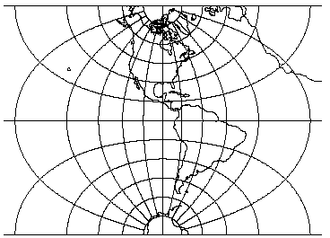
Transverse Mercator projection, Western hemisphere with shorelines and 15 degree graticule. Central meridian W90 (lon_0=W90).
Classifications: Transverse cylindrical. Conformal.
Aliases: Gauss Conformal (ellipsoidal form), Gauss-Kr¨uger (ellipsoidal form), Transverse Cylindrical Orthomorphic
This is a common projection for large scale maps of predominantly north-south extent..
|
Name |
Transverse Mercator |
|
Gauss-Kruger |
|
|
EPSG Code |
9807 |
|
GeoTIFF Code |
CT_TransverseMercator (1) |
|
OGC WKT Name |
Transverse_Mercator |
|
Supported By |
EPSG, GeoTIFF, PROJ.4, OGC WKT |
Projection Parameters
|
Params |
Name |
EPSG # |
GeoTIFF ID |
OGC WKT |
Units |
Notes |
|
Lat_0 |
Latitude of natural origin |
1 |
NatOriginLat |
latitude_of_origin |
Angular |
|
|
Lon_0 |
Longitude of natural origin |
2 |
NatOriginLong |
central_meridian |
Angular |
|
|
X_0 |
False Easting |
6 |
FalseEasting |
false_easting |
Linear |
|
|
Y_0 |
False Northing |
7 |
FalseNorthing |
false_northing |
Linear |
Universal Transverse Mercator (UTM) Projection
Projection: Transverse Mercator (Gauss-Krüger
type) in zones 6° wide.
Longitude of Origin: Central meridian (CM) of each projection zone (3°,
9°, 15°, 21°, 27°, 33°, 39°, 45°, 51°,
57°, 63°, 69°, 75°, 81°, 87°, 93°, 99°,
105°, 111°, 117°, 123°, 129°, 135°, 141°,
147°, 153°, 159°, 165°, 171°, 177°, E and W).
Latitude of Origin: 0° (the Equator).
Unit: Meter.
False Northing: 0 meters at the Equator for the Northern Hemisphere; 10,000,000
meters at the Equator for the Southern Hemisphere.
False Easting: 500,000 meters at the CM of each zone.
Scale Factor at the Central Meridian: 0.9996.
Latitude Limits of System: From 80°S to 84°N.
Limits of Projection Zones: The zones are bounded by meridians, the longitudes
of which are multiples of 6° east and west of the prime meridian.
Universal Transverse Mercator (UTM) coordinates define two dimensional, horizontal, positions. The sixty UTM zone numbers designate 6 degree wide longitudinal strips extending from 80 degrees South latitude to 84 degrees North latitude. UTM zone characters are letters which designate 8 degree zones extending north and south from the equator. Beginning at 80° south and proceeding northward, twenty bands are lettered C through X, omitting I and O. These bands are all 8° wide except for bond X which is 12° wide (between 72-84 N).
There are special UTM zones between 0 degrees and 36 degrees longitude above 72 degrees latitude and a special zone 32 between 56 degrees and 64 degrees north latitude:
UTM Zone 32 has been widened to 9° (at the expense of zone 31) between
latitudes 56° and 64° (band V) to accommodate southwest Norway.
Thus zone 32 it extends westwards to 3°E in the North Sea.
Similarly, between 72° and 84° (band X), zones 33 and 35 have
been widened to 12° to accommodate Svalbard. To compensate for these
12° wide zones, zones 31 and 37 are widened to 9° and zones 32,
34, and 36 are eliminated. Thus the W and E boundaries of zones are 31:
0 - 9 E, 33: 9 - 21 E, 35: 21 - 33 E and 37: 33 - 42 E.
Projection Parameters
|
Params |
Name |
EPSG # |
GeoTIFF ID |
OGC WKT |
Units |
Notes |
|
Zone |
UTM Zone Number |
Decimal |
||||
|
Lon_0 |
Longitude of natural origin |
2 |
NatOriginLong |
central_meridian |
Angular |
|
|
south |
Indicates map is in the southern hemisphere |
“south” |
||||
If both zone and lon_0 are used, +zone takes precedence.
For Southern hemisphere applications the option +south should be used which adds a false northing of 10,000,000m. In all cases, a false easting of 500,000m is used. Also see Universal Polar Stereographic (ups)
Mercator Projection
Mercator projection with shorelines and graticule Central meridian (lon_0) 90W
Projection Parameters
|
Params |
Name |
EPSG # |
GeoTIFF ID |
OGC WKT |
Units |
Notes |
|
Lon_0 |
Longitude of natural origin |
2 |
NatOriginLong |
central_meridian |
Angular |
|
Classifications: Conformal cylindrical.
PathAway Map Projection Library - Error Codes
| Description | Error Code |
| no arguments in initialization list | -1 |
| no options found in 'init' file | -2 |
| no colon in init= string | -3 |
| projection not named | -4 |
| unknown projection id | -5 |
| effective eccentricity = 1. | -6 |
| unknown unit conversion id | -7 |
| invalid boolean param argument | -8 |
| unknown elliptical parameter name | -9 |
| reciprocal flattening (1/f) = 0 | -10 |
| |radius reference latitude| > 90 | -11 |
| squared eccentricity < 0 | -12 |
| major axis or radius = 0 or not given | -13 |
| latitude or longitude exceeded limits | -14 |
| invalid x or y | -15 |
| improperly formed DMS value | -16 |
| non-convergent inverse meridinal dist | -17 |
| non-convergent inverse phi2 | -18 |
| acos/asin: |arg| >1.+1e-14 | -19 |
| tolerance condition error | -20 |
| conic lat_1 = -lat_2 | -21 |
| lat_1 >= 90 | -22 |
| lat_1 = 0 | -23 |
| lat_ts >= 90 | -24 |
| no distance between control points | -25 |
| projection not selected to be rotated | -26 |
| W <= 0 or M <= 0 | -27 |
| lsat not in 1-5 range | -28 |
| path not in range | -29 |
| h <= 0 | -30 |
| k <= 0 | -31 |
| lat_0 = 0 or 90 or alpha = 90 | -32 |
| lat_1=lat_2 or lat_1=0 or lat_2=90 | -33 |
| elliptical usage required | -34 |
| invalid UTM zone number | -35 |
| arg(s) out of range for Tcheby eval | -36 |
| failed to find projection to be rotated | -37 |
| failed to load NAD27-83 correction file | -38 |
| both n & m must be spec'd and > 0 | -39 |
| n <= 0, n > 1 or not specified | -40 |
| lat_1 or lat_2 not specified | -41 |
| |lat_1| == |lat_2| | -42 |
| lat_0 is pi/2 from mean lat | -43 |
| unparseable coordinate system definition | -44 |